Application Menu
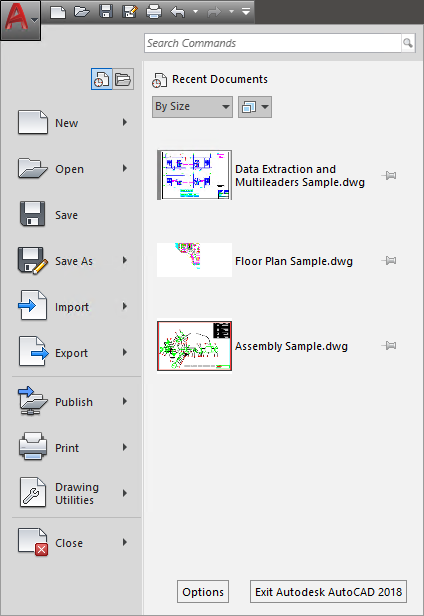
The first thing you might see after launching AutoCAD is the Application Menu, in the far upper left corner. In AutoCAD, it’s generally contains a big red “A”. (Other products generally have a different color and letter). When you single-click this button a menu drops down that contains some of the same items in the QAT, plus more. Probably more importantly, the application menu contains links to your most recently accessed drawings, and sheet sets. With the click of a button you can change this to a list of currently open drawings. (Tip: Do not double-click on the Application Menu button, unless you want to shut-down AutoCAD)
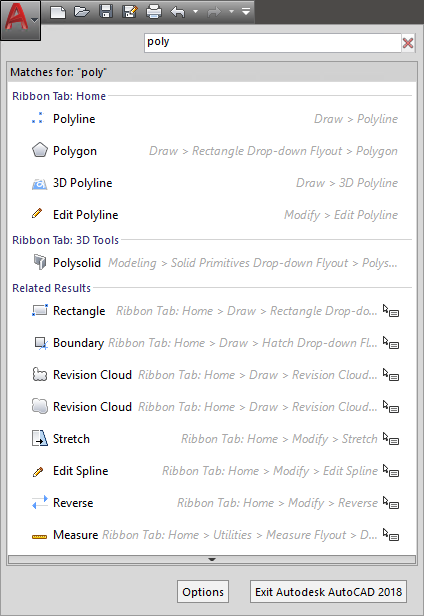
One feature of the Application Menu that many people overlook is the Search Commands portion. You can type in the full or partial name of any command and a search will be performed on the related commands in the menu. This can be helpful when you can’t quite remember that command name or its location. In the image below, we have entered “poly” in the search box, and you can see the results.
Quick Access Toolbar (QAT)
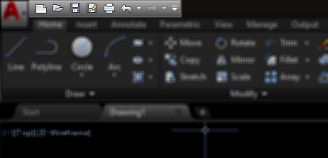
Right next to the At the top of the UI, in the title bar area, is the Quick Access Toolbar, or QAT. By default the QAT contains icons for the following commands: Qnew, Open, QSave, SaveAs, Plot, Undo, and Redo. But like most other UI elements, you can customize this to meet your desires. Below is the stock QAT, highlighted to show its position.
Ribbon
The ribbon is a UI tool that first appeared in AutoCAD 2009. It contains various commands organized into tabs and panels. It can be heavily customized by administrators and end users. Contextual tabs are very powerful, they appear with panels of commands and options relating to whatever task is at hand and/or whatever entity type is selected. For example, if a HATCH object is selected, a contextual tab with hatch editing command appears automatically.
In-Editor elements
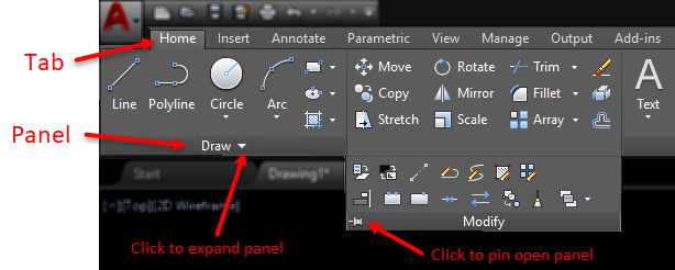
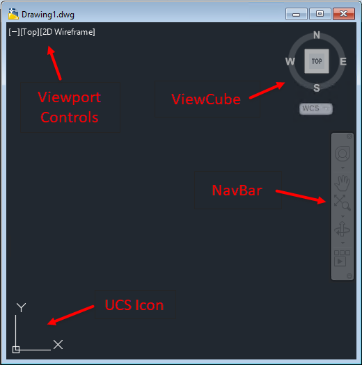
There are a few elements you may find inside the drawing editor, and are shown in their default location in the image below. The visibility of each of these can be controlled by the user. The viewport controls are in the upper left corner, and allow you to change the view and visual style. The Viewcube is in the upper right, from which you can change the view and UCS. Just below that is the NavBar, that gives you controls for zooming, panning, orbiting, and more. Lastly, in the lower left hand corner, is the UCS icon, which can tell you at a glance if you are in WCS, and/or the general orientation of the UCS.
Status Bar
Moving to the bottom of the application, you will find the Status Bar. Since AutoCAD 2015, the status bar contains icons only. By default several icons are not enabled, so you might want to turn them on. We believe Autodesk does this because on a small monitor, all of the icons may not fit across on one row. But the icons will wrap up to a second row if needed, and on any decent sized monitor these days, at 1920×1080 resolution, you can enable all of the status bar icons and they fit with ease.
Below is a stock status bar, along with the control icon ![]() on the far right, expanded to show you the other available icons (Click on the image below for a full size version)
on the far right, expanded to show you the other available icons (Click on the image below for a full size version)
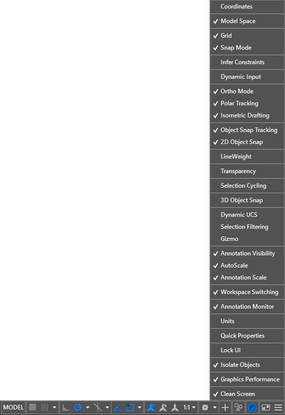
You can hover your cursor over each icon to find its purpose. Generally speaking, gray means the toggle is off, and blue means the toggle it on.
File Tabs
File tabs provide access to all open documents in a minimal amount of space. Each open document has its own tab. Left-click on a tab to make it current, and right-click on a tab to access more options, such as Save and Close. There is always a tab containing a plus sign to open a new document using the QNEW command. By default, File Tabs are oriented at the top of the documents, below the Ribbon.
![]()
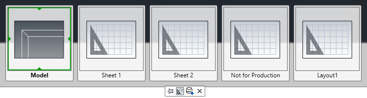
Layout Tabs
Layout tabs provide access to Model Space and each Layout in a given document. Left-click on a tab to make it current, and right-click on a tab to access more options such as Print, Move, or Rename. There is always a tab containing a plus sign for the creation of a new layout. By default, Layout Tabs are oriented at the bottom of the editor window and if the command line is docked, below that – in the status bar area.
![]()
Shortcut Menu
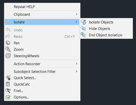
By default, with no command active, if you right-click in the drawing editor, you will get the Shortcut Menu. This pop-up menu contains recent commands, and other common commands. You can customize this menu, like most other UI items. If there is a command active, a different menu may appear when you right-click. This behavior is controlled by the SHORTCUTMENU system variable.
Drop-Down Menus
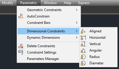
Drop-down, or pull-down menus have been around since almost the beginning of AutoCAD, long before Windows was a platform. A top level clickable name reveals commands and/or sub menus below. These commands support macros and even autolisp statements. The menu disappears when a command is selected and/or the menu loses input focus. Drop-down menus are not enabled by default. You can turn them on by entering the command MENUBAR and setting it to 1. An example of a drop-down menu can be found below:
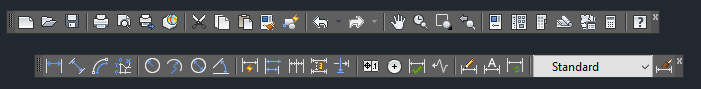
Toolbars
Toolbars go back to the early 1990’s in AutoCAD. These are flat panels that contain buttons and or drop-down lists. Each button contains an icon and a macro to perform a command or macro. Toolbars can be floating or docked.
Palettes
There are various palettes available in AutoCAD. Palettes are special windows that can docked, floating and made to collapse when not in use. You do not have to close palettes in order to work with graphic data on screen. Most palettes support transparency (with proper hardware support) to allow them to remain on screen during AutoCAD commands.
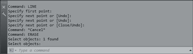
Command Line
The command line is a palette where you can type in command names and/or command responses, and the view the history of both. If the command line is docked, it has a fixed number of visible lines. Floating command line palettes can expand when needed to show you more data. The F2 key in both cases will toggle open/closed, a larger command line history window. A typical floating command line is shown here:
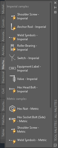
Tool Palette
Tool Palettes contain buttons to insert blocks, execute commands, create hatches, just to name a few items. Users are free to customize the content. A sample is shown below:
Sheet Set Manager
The Sheet Set Manager is a tool that allows you to organize sheets, streamline printing and archiving, and automate annotation on drawing sheets among other uses. A sample is shown below:

There are many other palettes, such as the Quick Calculator, Drawing Recovery Manager, Visual Styles Manager, the Materials Browser, etc.
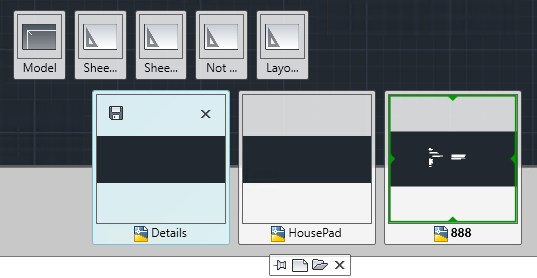
Quick View Drawings
Before File Tabs, there was Quick View Drawings. Although no longer enabled by default as a UI element, this command still works from the command line (Command: QVD). It reveals a miniature preview of each open document, and allows you to switch to another document. As the mouse is hovered over a document preview, the layouts of that drawing appear, allowing you to switch directly to a selected layout.
Quick View Layouts
Introduced as sort of replacement for Layout Tabs, Quick View Layouts has suffered the same fate as Quick View Drawings. That is to say it is still part of the software, but hidden away. This command (QVL) reveals miniature previews of all of the layouts of the current open document. Hover over a preview enables the option to print it, or clicking on one switches to that layout.
InfoCenter
InfoCenter has been through a few iterations and name changes since it was introduced. It resides in the Title Bar area, just to the left of the Windows control buttons. It contains a help search bar, Autodesk A360 sign in, social media links, and a Help drop-down menu. InfoCenter has been linked to excessive “phoning home” and is frequently disabled and hidden by many CAD managers. There is no UI method of controlling the visibility of this element, it must be done in the registry, or with a 3rd party add-on such as this one. Below is the default InfoCenter bar.
![]()
Screen Menu
The Screen Menu goes back to the beginnings of AutoCAD on DOS and UNIX. The Screen Menu is composed of nested menus. Clicking on one entry usually replaces the screen menu contents with another menu, until you get to a particular command. There is always a back and/or home choices too. Most people do not know it still exists in AutoCAD 2018 today. To access it, you must know the secret code.
Well, it is not too secret, just type in: (setvar “screenmenu” 1)
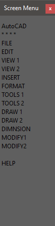
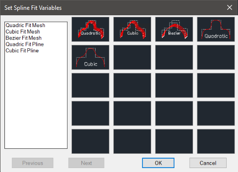
Image Tile Menu
Last, but not least, unless you’ve been around for ~20 years or so, you have probably never seen an Image Tile Menu. We were able to actually get one of these to work in AutoCAD 2018 as seen below. These were largely replaced by Tool Palettes and DesignCenter around the AutoCAD 2000 era.
Thanks for reading this lengthy post. What did we miss? Are there other elements that you use? Let us know!


Visitor Rating: 5 Stars
Visitor Rating: 5 Stars
Visitor Rating: 5 Stars
Visitor Rating: 5 Stars