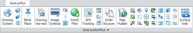
To get started, most functionality in GeoLocationPlus requires that you set your coordinate zone. To do this, click the first button on the Ribbon named Drawing System.
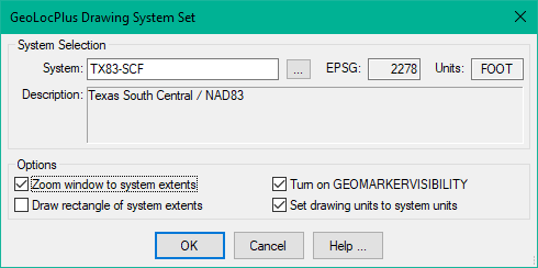
If you know the name of your zone, simply type it into the top field and press the Tab key. The other read-only fields in this dialog will be populated. If you don’t know the zone name, click the button next to the blank field and find your desired zone in the “Coordinate System Select” dialog. In our example, we will use TX83-SCF (Texas State Plane South Central Zone, NAD83, Foot).
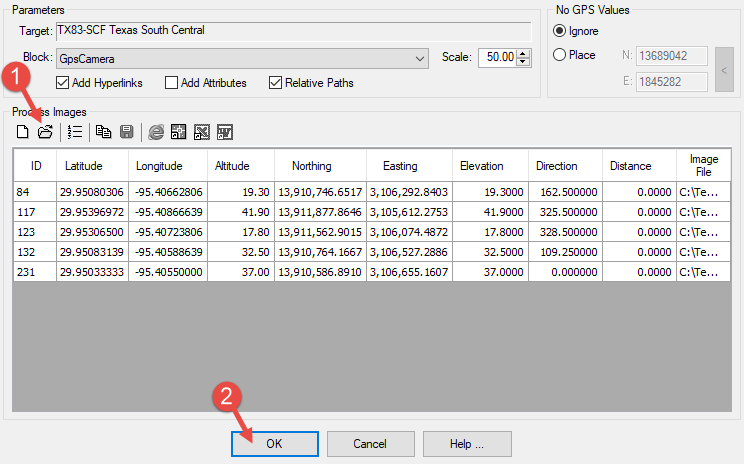
Now that we have the Coordinate Zone set, let’s look at the “Image Symbol Place” command. This command will place a symbol at the location of a captured image, presuming that the image contains the required GPS information. Almost all cell phones and some traditional cameras include the GPS data in the embedded EXIF data. No special file preparations or external “world” files are needed. After launching the command, click the open button (1) to select your images. After reviewing the data and other options such as block name and scale, press OK (2).
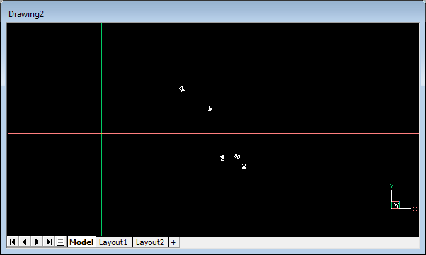
The selected block will be inserted at the correct northing and easting locations. Below is our drawing with our five blocks inserted.
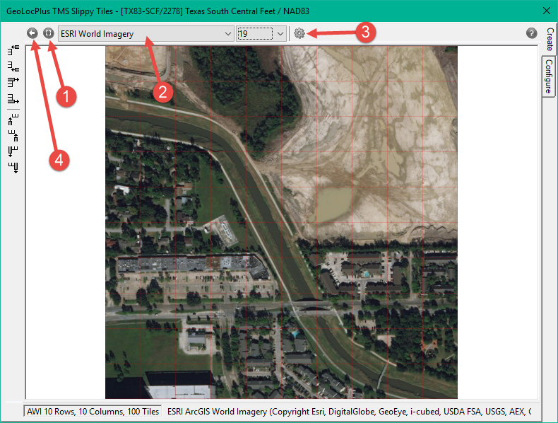
Hmmmm…. not much information and not very helpful so far, right? Ah, just wait. Let’s add in a some background aerial imagery. Just the the right of the Image Symbols command on the GeoLocPlus ribbon is the “Image TMS Tiles” command. Fire this up and operate this command as shown in the image below.
- Select the area in your drawing to cover with the aerial imagery. Your situation may be different, but in our example here, that is why we inserted the image blocks first.
- Select the type of imagery to insert, we’ll use the ESRI World Imagery.
- Load the imagery into the dialog for review.
- Insert the imagery into the drawing after you have reviewed it.
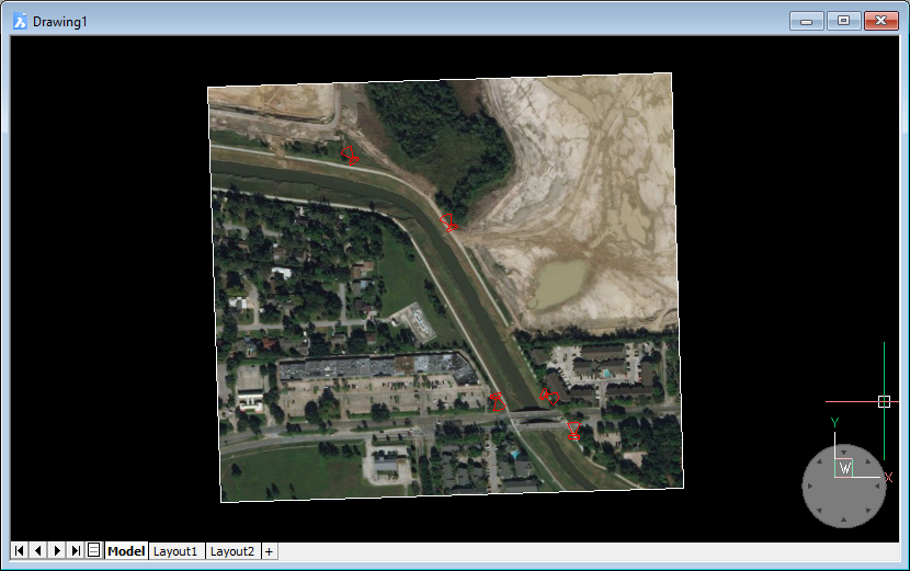
After inserting the imagery, we changed the color of the image blocks to red. Here is the result. As you can see, our photos were taken along the channel shown in the aerial image.
Now comes the cool part. Back to the GeoLocationPlus ribbon, click the button just to the right of “Image Symbols”, at the top. This will open the resizeable IMAGELINKS window. Now move your cursor over one of the image blocks. Voila, the picture you took at that spot shows up.
Inserting and viewing GPS images into your CAD drawings is only one of the many functions of DotSoft’s GeoLocationPlus add-on. Click on the link to read about all of the other functionality and to see if your CAD platform is supported. If you have a question or comment, please leave a reply below.