A LINE is one of, if not the, most basic CAD entities. A LINE is simply defined by two points. There are other properties such as layer, color, and linetype, but if you have two points, you can create a LINE in CAD.
Despite its simplicity, here are 5 things you can do with the seemingly simple old LINE in CAD. All of these apply to AutoCAD and BricsCAD.
- Okay, so we cheated on #1. Draw a standard line. Pick two points and you’re done. It couldn’t be any easier.
- Lines can be drawn on any plane, not just the current working plane. Presuming that you are working on the standard XY plane, you can use point filters or object snaps to create different “Z” value for one or both endpoints, which will create a line with a slope. Unlike 3D Polylines, 3D lines will display the correct linetype. Take a look at the animation below. The top line and the rectangle are on the same plane.
3. Lines can have a thickness > 0.0 No, we are not talking about the thickness you see when you print, the thickness we are talking about might better be named “Height”. See the animation below.
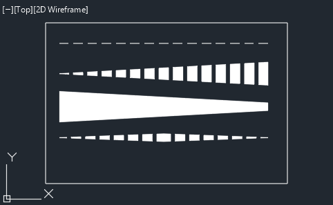
4. Like most other entities, LINEs can have a line weight applied to them. But what if you want a varying width to your line? You have to cheat a little again and convert the LINE into a POLYLINE, but then you can create objects as shown below. See also this post on how to create a “faded” line.
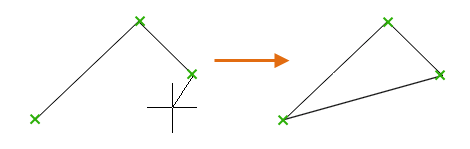
5. If you are drawing multiple lines within the same command, you can use “C” after the second line segment to close a polygon, just like you can with the POLYLINE command. Using “C” to close a polygon does not create a POLYLINE, you still get separate LINE entities.
So what else can you do with LINE objects?